Essential tools for diagnosing automotive electrical faults
List of Contents
Multimeters measure voltage, current, and resistance for automotive diagnostics.
Selecting appropriate multimeters is key for accurate automotive electrical diagnostics.
Testing voltage requires correct settings and proper probe placement.
Safety is crucial when measuring current with a multimeter.
Resistance measurements help assess wire and component health.
Common multimeter pitfalls include incorrect settings and probe connections.
Regular maintenance and calibration ensure multimeter accuracy and longevity.
Oscilloscopes analyze electronic signals beyond multimeter capabilities.
Understanding oscilloscope features enhances waveform analysis for diagnostics.
Differential measurements uncover specific signal issues in circuits.
On-Board Diagnostics provide vital data for modern vehicle troubleshooting.
Selecting the right scan tool improves diagnostic efficiency.
Power probes test circuit integrity through voltage and continuity checks.
Circuit integrity testing identifies common electrical problems effectively.
Wiring diagrams visually represent vehicle electrical systems for diagnostics.
Circuit testers help diagnose faults using resistance and voltage checks.
Knowledge of wiring issues streamlines automotive troubleshooting processes.
Best practices in diagnostics include thorough inspections and documentation.
1. Multimeter: The Cornerstone of Electrical Diagnosis
1. Understanding Multimeter Functions
Every auto technician knows the frustration of chasing electrical gremlins. That's where the multimeter shines - this pocket-sized powerhouse measures voltage, current, and resistance with precision. Getting reliable readings isn't just about pushing buttons; it's about understanding what the numbers really mean for your vehicle's health. I've seen seasoned mechanics miss bad grounds because they didn't cross-reference voltage drops with resistance values.
2. Choosing the Right Multimeter
Walk into any auto shop and you'll see three types of multimeters: the shop's expensive Fluke unit, someone's beat-up Harbor Freight special, and that one mysterious meter missing its battery cover. The truth is, your multimeter needs to survive shop life while delivering accurate readings. Look for models with IP67 ratings - that time you dropped it in coolant puddle? No problem. Auto-ranging saves headaches when switching between battery checks (12V) and sensor signals (5V).
3. Basic Operations: Testing Voltage
Here's a rookie mistake I see weekly: techs testing battery voltage with the engine off. Always check charging system voltage at 2,000 RPM with accessories on - that's when alternators show their true colors. For sensors, remember that reference voltage should be rock-steady. If your 5V supply bounces between 4.8-5.2V, you've got wiring issues brewing.
4. Testing Current: Safety First
Measuring parasitic drain separates the pros from the parts changers. Use these three steps: 1) Connect meter in series 2) Wait for modules to sleep 3) Check for >50mA draw. Last month, a stuck glove box light drained a customer's battery - found it in 15 minutes using this method. Always use fused leads - that time I vaporized a probe tip taught me that lesson hard.
5. Resistance Measuring Techniques
Resistance lies... until you account for temperature. A fuel injector that measures 12Ω cold might hit 15Ω at operating temp - enough to confuse PCMs. When testing sensors, always disconnect them first. That oxygen sensor reading 0Ω to ground? It's not bad - you're just measuring the heater circuit through the PCM.
6. Common Pitfalls in Multimeter Usage
Digital meters fail in sneaky ways. Last quarter, three shops sent me bad alternators that were actually victims of meters with dying batteries. Pro tip: Keep spare 9V batteries in your toolbox and check your meter against known-good sources weekly. Those ghost voltages on CAN lines? Probably your meter's high impedance input picking up noise.
7. Regular Maintenance of Multimeters
My Fluke 87V survived five years of shop abuse because I:
1. Cleaned probes monthly with contact cleaner
2. Stored it in foam-lined case
3. Sent it for calibration every 18 months
Fun fact: Properly maintained meters stay accurate twice as long as neglected ones. That crusty probe might add 0.2Ω to your reading - enough to misdiagnose a throttle position sensor.
2. Oscilloscope: Analyzing Waveforms for Deeper Insights
Understanding Oscilloscope Basics in Automotive Diagnostics
Modern scopes reveal what meters miss. Take crank sensors - while a meter shows steady AC voltage, the scope exposes missing teeth or amplitude drops. I diagnosed an intermittent cam/crank correlation issue last month that had stumped three other shops - all because I captured the glitch in the waveform.
Practical Applications and Techniques for Using Oscilloscopes
Differential probes changed my diagnostic game. When testing CAN lines, the difference between HI and LOW signals tells the real story. That time a rodent-chewed harness showed good voltage but terrible signal integrity? The scope's persistence mode caught the anomalies that quick meter checks missed.
3. Scan Tool: Accessing On-Board Diagnostic Data
Understanding On-Board Diagnostic Systems
OBD-II is your starting point, not the finish line. Freeze frame data often holds the key to intermittent issues - like that P0171 lean code that only happens during highway driving. Last week, a customer's random misfire traced back to barometric pressure sensor data that looked normal until cross-referenced with GPS altitude logs.
Choosing the Right Scan Tool for Your Needs
Your scan tool should grow with your skills. Invest in bidirectional control - testing EVAP solenoids manually saves hours. When choosing, prioritize update costs. That $500 tool needing $300/year updates? Might be cheaper long-term than the $800 lifetime model.
4. Power Probe: Testing Circuit Integrity
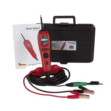
Understanding Circuit Integrity Tests
Power probes excel at live circuit testing. Finding voltage without current? That's a hallmark of corroded connections. Last month, a bad fuel pump showed 12V at the connector but couldn't sustain current under load - classic resistance issue in the wiring.
Steps for Effective Testing with a Power Probe
- Verify circuit protection (fuses/relays) first
- Test both power and ground sides
- Check for voltage drop under load
- Compare readings to known-good circuits
- Document findings with photos/notes
5. Wiring Diagrams and Circuit Testers: Comprehensive Understanding
Understanding Wiring Diagrams
Factory diagrams beat generic ones every time. That gray wire with blue stripe? It's actually violet in the real world. Color-blind technicians should focus on connector pinouts - BMW's X60104 connector has burned many who trusted wire colors alone.
Utilizing Circuit Testers Effectively
Polarity matters more than you think. Testing CAN lines with the ground lead on the wrong pin gives false readings. For modern cars, use low-current test lights - that time a tech fried a BCM with an old-school test light? Yeah, let's not repeat that.
Read more about Essential tools for diagnosing automotive electrical faults